Our email address has changed!
We can now be contacted at sales@huttonwinches.com.
Please use this email address for all further enquiries.
HUTTON BoomBrake Fitting Instructions
Please read all instruction carefully before you begin fitting your BoomBrake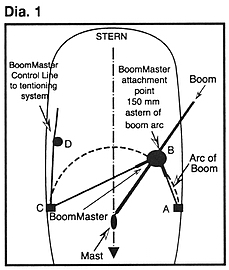
Refer to diagram 1.
a) Determine the two strongest points to anchor the fastenings for the BoomBrake
Control Line (A & C).
The aft most chain plate is ideal, but a well affixed metal toe rail can be
used. However, it is well to remember that considerable forces can be generated
at the point of attachment.
If in doubt as to the strength or suitability of any selected fitting method,
seek professional advice.
In some cases, for example where the point of attachment is through a deck or
cabin top, it is wise to fit a reinforcing plate behind the point of attachment
in order to spread the load.
Chain plates can be drilled to allow for the fitting of a sturdy shackle.
b) Select (A or C) the point to which you will tie off
your BoomBrake Control Line.
On the opposite of the vessel, affix (by a shackle) a swivel metal sheathed
turning block to the attachment point (A or C)
Refer to diagram 2.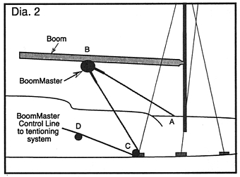
Positioning the BoomBrake at the right position on the boom is important.
Mark a point on your boom which is directly above the attachment point (A
or C). Measure from this point 150mm (5-7/8") aft along the boom and
mark this point as teh point of attachment on the boom for your BoomBrake
(B).
c) The BoomBrake is affixed to the underside of the boom (B).
Use a sturdy attachment such as is used for attaching a conventional boom vang
or for a mainsheet attachment.
Again, remember that the load on this attachment point can be considerable.
d) Affix the BoomBrake attachment fitting to the boom (B).
By using a swivel, affix the BoomBrake unit to the boom fitting (B).
Fitting the HUTTON BoomBrake Control Line
e) The Control Line should be a pre-stretched 'Dacron' type rope. The
rope size will depend on the BoomBrake model and size of the sail you
wish to control:
Model M100: Rope size 6mm to 10mm [1/4" to 3/8"]
Model M125: Rope size 8mm to 13mm [5/16" to 1/2"]
Model M150: Rope size 10mm to 15mm [3/8" to 9/16"]
f) Affix one end of the BoomBrake Control Line to your chosen
attachment point (A or C).
Ensure that the rope will not chafe.
g) Lead your Control Line from the fixed point (A or C)
up and through the guide hole in the end of the guide arm.
Feed the line around the helical drum so the the line lies in the machined
groove.
Continue to feed the line back down through the other guide hole in the opposite
guide arm.
The line then continues to the turning block and is fed through this block.
From here it is usual to lead the Control Line aft to the cockpit, or some other area, from where it is easy to control the BoomBrake Control Line, using a small winch or purchase block system.
Note: On racing yachts and larger vessels using the Model M150, it may be desirable to run the Control Line aft to the cockpit on both sides of the boat, so that the Control Line can be tensioned from either side of the BoomBrake helix.
h) Once your BoomBrake is installed, check all fixings and attachment points to see that the Control Line is secure at the originating point and that it can run freely trough the blocks etc, back to the cockpit.
Now you are ready to sail with your HUTTON BoomBrake - fair winds!
THE AUSTRALIAN YACHT WINCH PTY. LTD.
PO Box 401
Galston N.S.W. 2159 Australia
Phone: +61 2 9653 2111
Fax: +61 2 9653 3119
Email: sales@huttonwinches.com
All prices quoted on this site, unless otherwise specified, are in US dollars.
© Australian Yacht Winch Pty. Ltd.